Computer & Electronics
ideflasher, what is that?
It's an inventive simple solution
for writing flash ROM devices
It's a low-priced multi-IO-card
Enabling multipurpose operations through use free programmable IO-ports
last change: 2003/07/20
BIOS update failed?
What's happend? Has your update failed due wrong BIOS image? Have you got the right BIOS version for this board? What will happen if BIOS update is interrupted due power failure? Normally your computer will neither start up nor give a single beep.
When this happends you need to reprogram your BIOS chip. You could do this by sending your chip to a specialist company or by obtaining a replacement from the motherboard manufacturer. The ideflasher is an alternative. Together with another computer you can easily reprogram the BIOS chip by yourself.
Flash memory devices are not only used in ordinary PCs. Today a lot of devices are sold with built in flash memory e.g. DVD player, network adapter or telephone systems. Embedded systems like digital cameras use this type of memory. Sometimes it is also possible to insert a flash ROM as BOOT-ROM to older network adapters which normally uses EPROMs. On the market you will find a lot of devices which use flash memory.
Project: ideflasher
The ideflasher PCB is the simplest type of a flash ROM reader/writer for a PC yet made. You need not to be an expert to assemble it by yourself. It just need a few hours to assemble your own version. It takes approximately 1-5 h; soldering ability required. The ideflasher tool doesn't need a free ISA- nor- PCI slot. Just connect it to a free IDE-port.
The basic idea is to use a 82C55-PIO as main controller. This IC offers 24 free programmable IO-ports. Beside using it as a flash ROM programmer, this gives a high flexible interface for applications like:
- model railway communication
- GAL progammer
- relay switching boards
- EPROM programmer
- capacitor identification
- analog-digital and digital-analog converter
- LCD or LED display driver
- ...
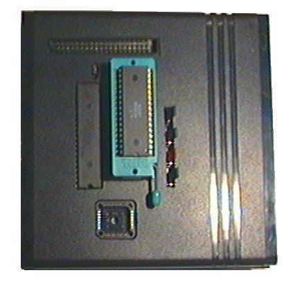
Over the last few years many motherboards use flash ROM with PLCC32 pinout. This PCB board provides both commonly used sockets, a DIP32 and PLCC32 socket. Thus, you can handle flash ROM circuits in both pinouts without an expensive adapter.
The ideflasher is designed to use flash ROM with 5V or 12V programming voltage. Through available sockets the ideflasher may programm circuits up 4 MBit (=512kByte) by default. Flash ROM that comes in other pinouts can be programmed in principle. The problem is not the capabilities of the ideflasher but more the high prices of adapters for other pinouts like TSOP etc.
Main purpose for ideflasher is supporting updates of BIOS, firmware of DVD-Players or ModChips. Almost all motherboard manufacturers offer appropriate BIOS images on their sites. Occasionally you can download ROM-Images for DVD-player or other devices from internet.
Before starting to flash new code to ROM, it is a good idea to save the old content to disk or even better copy the new code to a second chip and try it first, to make sure the update is working.
EPROM, EEPROM, Flash ROM
Today usage of flash ROM exceed those of their predecessors EPROM. For many cases
they are the better solution. Often it is even possible exchange older EPROM to flash ROM
to get most of their advantages.
Like EPROM, it is used to store permanent data. But flash ROM haven't the disadvantage using
special UV-lamp to erase data and doesn't need special voltage (12,5V) to rewrite data. Ordinary
power supplies provide only 5V and 12V. It that situation EEPROM were more convient thay just need a electrical impulse
instead of UV-light to erase all the data. Nevertheless you need special programming hardware.
Flash ROM has none of the these disadvantages. They have a faster access time and
with low expenses data can be rewriten again and again.
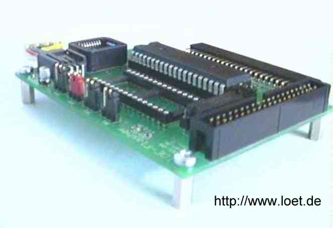
Ideflasher kit
The c't-Flasher project from a german computer magazine c't 16/1997 gave the
inspiration to design a new circuitry that is less complex and low in price. As a result it
can be easily assembled by hobbyist with little effort and finally it costs just a few Euro.
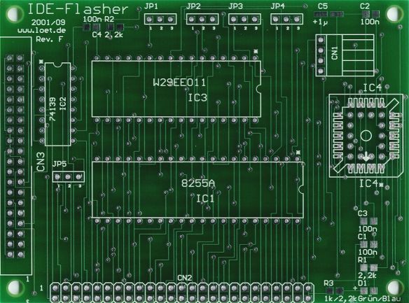
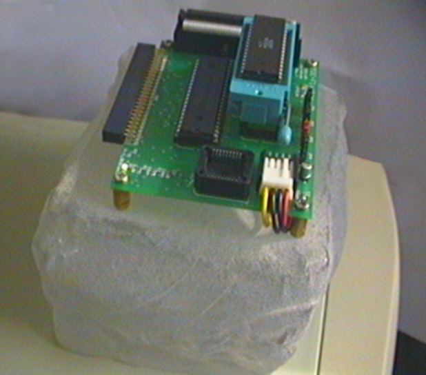
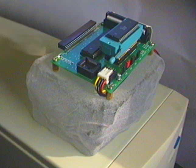
Three public modifications of the ideflasher device has been designed; RevD, RevE and RevF. The early version
RevD possessed a 5,25" drive power connector. Some ideflasher had a cool blue LED as
power indicator. Since late RevE there is an additional expansion board for own extensions.
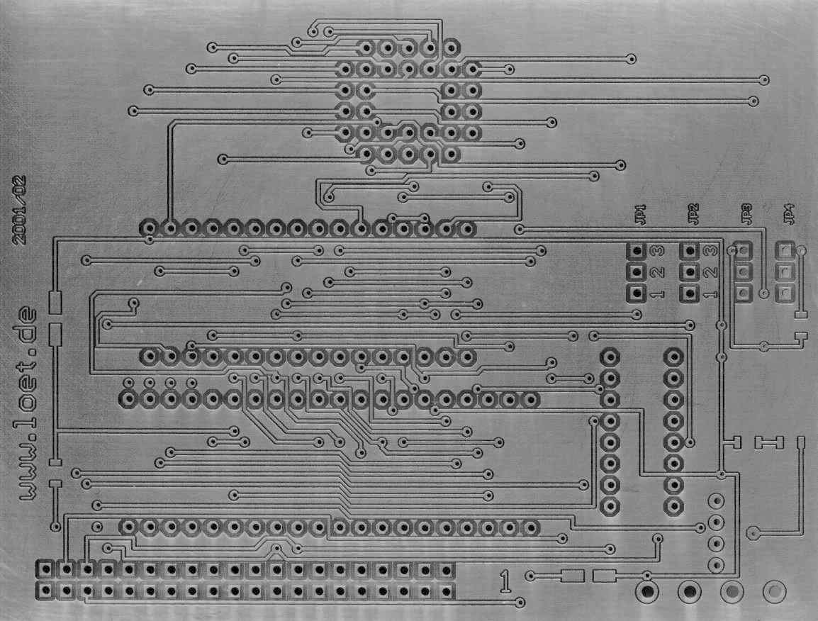
schematic und revisions
|
schematic software parts list |
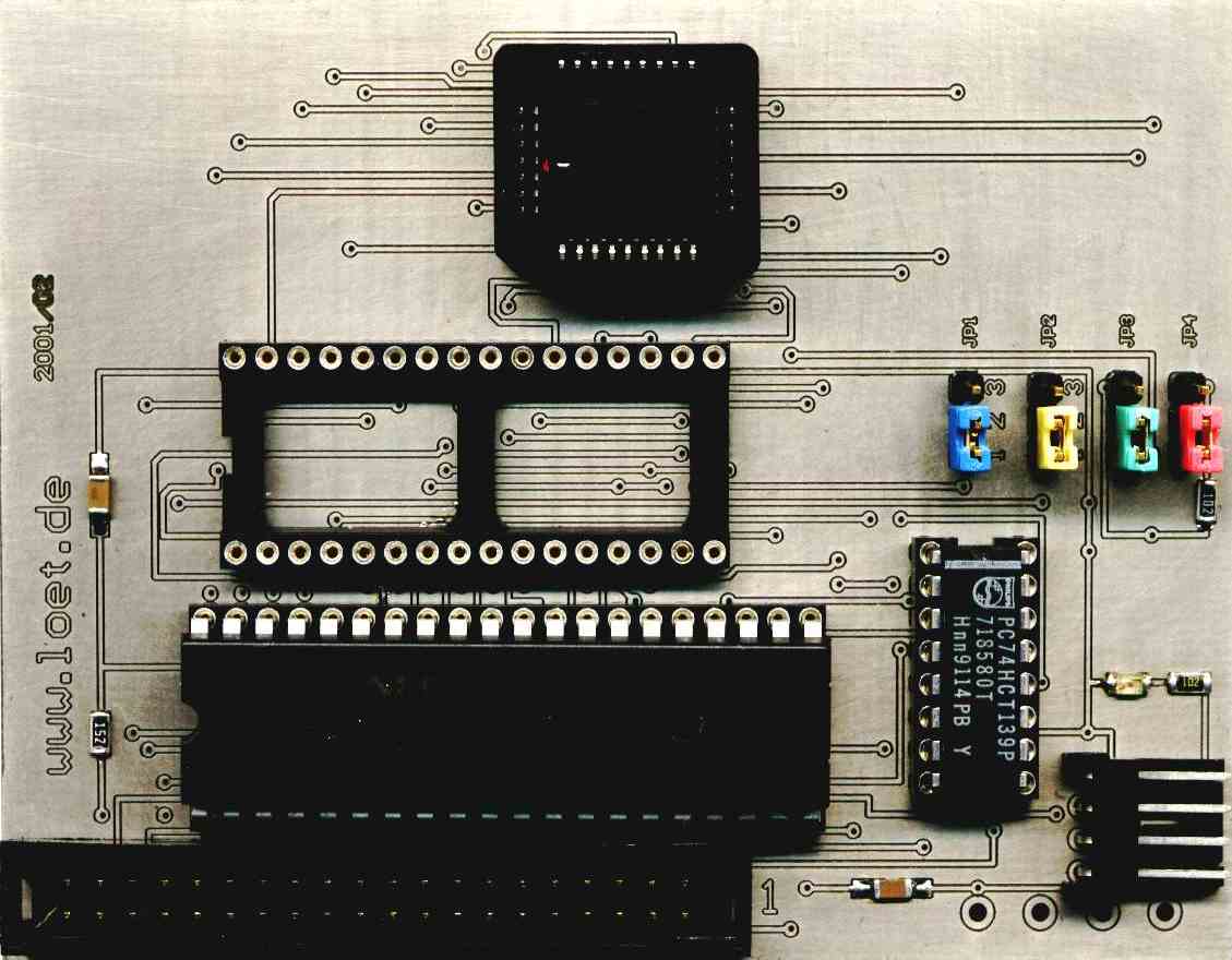 RevD unpopulated 2001 |
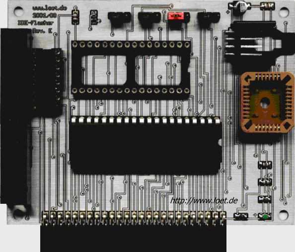 RevE 2001 |
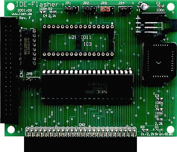 RevF unpopulated seit 2002 | |
installation suggestions
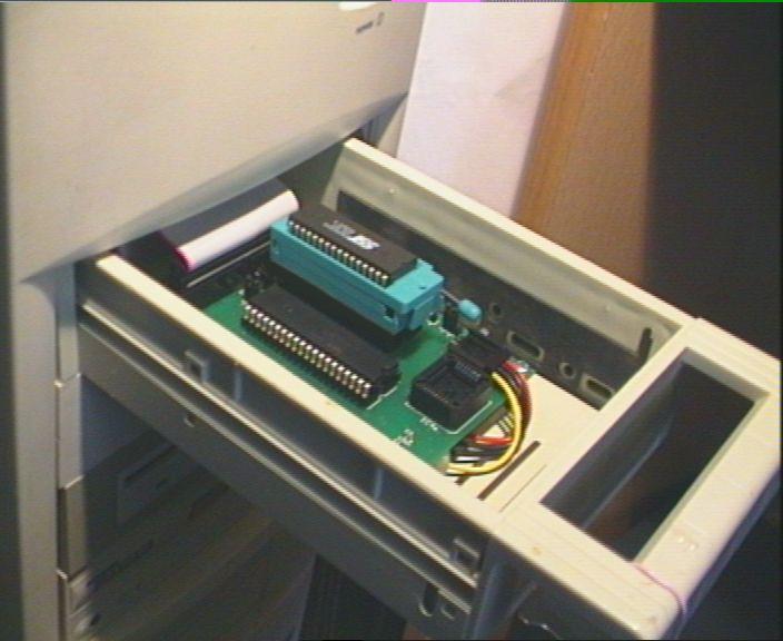 interchangeable harddisk case1 |
 installation kit |
 designer sandbad cast glas cube |
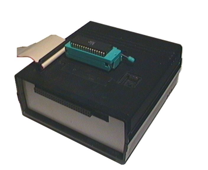 TEKO 011 case1, 2 | ||||
| |||||||
Costs, Ordering, PCB
Purchases are very low. The more courageous among us don't need any resitors or capacitors, only 82c55 PIO, 74HCT139 and a 40pin male IDE-connector. For less then 5 EUR you can solder an ideflasher by yourself. It may not look very beautiful, but a simpler solution isn't possible. All other items may ordered via online shop.
Questions, Indices, Contact
If you need more information, build up your own version, (inquiring questions are welcome) please let me now or give a short note: